Quick Summary: Torque vectoring is a system that decides which wheel gets power and when — reading yaw rate, wheel speed, steering angle, and lateral forces hundreds of times per second to keep your car on its intended line. Brake-based torque vectoring is now standard on Indian SUVs like the Mahindra XUV 7XO. The Skoda Kodiaq uses a mechanical Electronic Differential Lock. EVs will make this technology far more sophisticated. This article explains the hidden math, the software logic, and why it matters particularly on Indian roads — and what used car buyers should check before buying any AWD SUV in India.
You are driving on a rain-slicked stretch of the Bengaluru-Mysuru expressway. You take a sweeping left-hander at speed. Somewhere inside your car, in a span of milliseconds, a control unit has read your steering angle, measured the rotational difference between your four wheels, noted that the road surface is slippery, estimated the risk of the rear stepping out, and quietly applied a precise braking force to one specific wheel to keep the car on its intended line.
You felt none of this. The car simply turned the way you wanted it to. That is torque vectoring at work — and it is now appearing in Indian SUVs at price points that would have seemed unlikely just five years ago.
What Torque Vectoring Actually Is
The concept is straightforward: instead of sending equal power to both wheels on an axle, torque vectoring actively directs power to the wheel that can most usefully deploy it.In a standard car with a conventional differential, power is distributed to the wheels in a roughly equal split. A conventional open differential allows each wheel to spin at different speeds when cornering — which is why your car can turn at all. But it cannot control which wheel receives more torque. In situations where one wheel has less grip than the other — wet road, loose gravel, a cambered surface — equal torque distribution becomes a liability. The wheel with less grip spins uselessly, the wheel with more grip sits idle, and the car understeers or oversteers.
Torque vectoring solves this by actively distributing torque to the wheel or wheels that can most usefully deploy it. The result is a car that stays on its intended line more precisely, uses available traction more efficiently, and responds to driver inputs with less drama in difficult conditions.
The Two Main Approaches in India
Two fundamentally different methods of achieving torque vectoring are present in cars sold in India today — one software-dominant and one mechanically-driven.Brake-Based Torque Vectoring
This is the more common and more affordable approach. Rather than physically sending more power to a specific wheel, the system uses the existing brakes to slow one wheel selectively. When the system detects the inside front wheel receiving more torque than it can use during cornering, it applies a brief, precise braking force to that wheel — effectively transferring more drive to the outside wheel and pulling the car through the corner rather than pushing it wide.
The Mahindra XUV700 and its updated successor the XUV 7XO, launched in January 2026, use brake-based torque vectoring via the ESP suite, which includes torque vectoring by braking alongside traction control, vehicle dynamics control, hill descent control, and roll-over mitigation. This is a software-dominant system — the hardware already exists on the car for safety purposes. Torque vectoring by braking is, in essence, a calibration and software decision layered on top of existing brake infrastructure.
Mechanical Torque Vectoring
This approach uses clutch packs, gear sets, or dedicated differentials to physically transfer torque between wheels rather than slowing one of them. The advantage is that the system can accelerate a wheel, not just slow one down, making it faster and more precise. The Skoda Kodiaq — priced from Rs 39.99 lakh in India — uses an Electronic Differential Lock alongside its AWD system that intelligently distributes torque to the wheels with the most grip, allowing it to manage technical terrain and demanding road conditions without requiring driver intervention.
The Software Layer: How the ECU Decides
The mechanical or brake-based hardware is the actuator — the software is the intelligence that decides when and how much to act, reading multiple inputs hundreds of times per second.A typical torque vectoring control unit reads wheel speed sensors, a yaw rate sensor measuring how quickly the car rotates around its vertical axis, a lateral acceleration sensor measuring sideways forces, the steering angle sensor, and throttle position. From all of this, the ECU builds a real-time model of what the car is doing versus what the driver intends. If the actual yaw rate is less than what the steering angle and speed suggest it should be — understeer — the system can apply braking to the inside rear wheel to rotate the car more. If the actual yaw rate is greater than intended — the rear stepping out — it can brake the outside rear wheel to stabilise. All of this happens before the driver perceives anything unusual.
The calibration of this system is where carmakers invest enormous engineering effort. Too aggressive, and the system feels intrusive. Too conservative, and it does not intervene early enough. The balance point differs by vehicle type — an off-road SUV like the Mahindra Thar needs a system that allows significant wheel slip before intervening, while a road-focused SUV like the Skoda Kodiaq needs sharper, faster intervention to stay composed on wet tarmac at highway speeds.
Why Indian Roads Make This Technology Particularly Relevant
In India's driving environment, where road surfaces, weather conditions, and traction situations change without warning, torque vectoring provides something more fundamental than refinement — it provides safety in conditions that cannot be anticipated.A driver going from a dry expressway into an unexpected water crossing near Pune does not have time to consciously adjust throttle inputs and steering. The torque vectoring system has already registered the wheel speed differential and redistributed torque before the car can step out. Speed breakers create brief moments where weight transfer dramatically shifts the traction balance. Uneven state highway surfaces mean individual wheels regularly encounter different grip levels simultaneously. Sharp ghats in places like Munnar, Coorg, or the Himachal Pradesh hills create sustained cornering situations where inside and outside wheels are under very different loads.
Torque vectoring — particularly the brake-based version now standard on vehicles like the Mahindra XUV 7XO — addresses each of these situations through continuous, invisible software management that no amount of skilled driving can replicate at human reaction speeds.
The EV Dimension: Torque Vectoring Gets Easier and More Powerful
Electric vehicles change the torque vectoring equation fundamentally — an electric motor responds to a software command in milliseconds, giving the control system a level of authority over wheel torque that no mechanical drivetrain can match.A conventional engine connected to a mechanical drivetrain takes time to respond to a software command — there is inertia in the rotating components, response lag in the throttle, and limits on how fast power can be changed. An electric motor responds in milliseconds. An EV with individual motors on each wheel can apply a precise torque command to each wheel independently without any mechanical coupling between them. Even the simpler twin-motor AWD layout — one motor front, one rear — allows the software to split torque front-to-rear almost instantaneously, with far more precision than any mechanical differential allows.
Indian EVs are not yet widely offering sophisticated multi-motor torque vectoring, but the architecture that enables it is arriving. As electric powertrains become more common in Indian SUVs over the next three to five years, the gap between what a software-controlled electric drivetrain can do and what a mechanical one can do will become increasingly visible in real-world driving.
The Calibration Difference Between Road and Off-Road Systems
One of the least-discussed aspects of torque vectoring is how differently it must be calibrated for road versus off-road use — and why buying the wrong system for your actual use case matters.A road-optimised torque vectoring system intervenes early and aggressively, tuned to keep the car stable at highway speeds and cornering forces well within the tyre's limits. For a family SUV doing highway runs between Jaipur and Delhi, this is exactly right. An off-road system must allow significantly more wheel slip before intervening. When a Mahindra Thar is crossing a rocky section on a Himachal Pradesh trail, the wheels need to be allowed to spin — traction comes from finding grip and digging in, not from the software cutting power the moment a wheel loses contact.
This is why the XUV 7XO's brake-based torque vectoring is tuned for road dynamics while the Thar's four-wheel-drive is tuned for terrain. Neither is better — they are calibrated for fundamentally different physics and different buyer intentions.
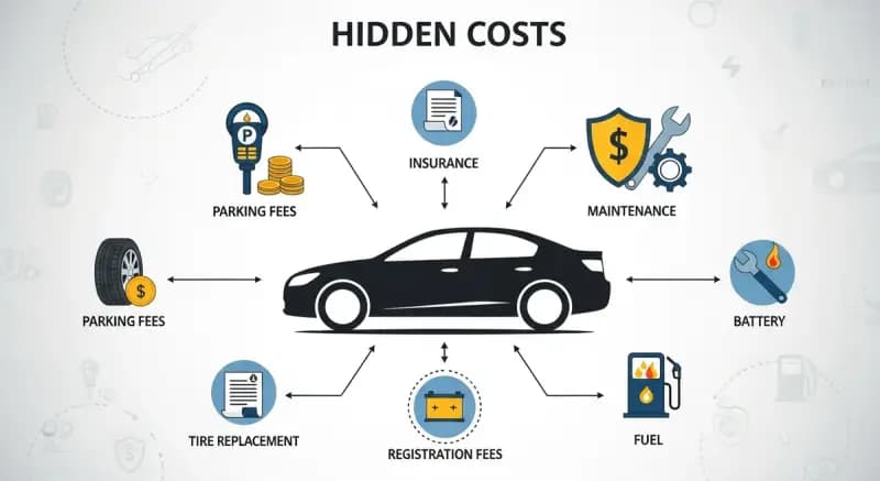
What It Means for Used Car Buyers in India
Torque vectoring is a software and hardware-dependent system — and a used AWD SUV with a faulty ESP sensor or worn brakes is not just impaired, it may be actively dangerous.Brake-based torque vectoring depends entirely on the braking system working precisely. A used Mahindra XUV 7XO AWD with worn, unevenly-weighted brake pads or a malfunctioning wheel speed sensor will not torque-vector correctly — the system may apply correction at the wrong moment or with the wrong intensity. Before buying any used SUV with torque vectoring, a pre-purchase inspection should specifically verify the ESP system is functioning correctly, all four wheel speed sensors are operational, and the brake system is in uniform good condition across all four corners.
For mechanical AWD systems — clutch-pack based differentials in vehicles like the Skoda Kodiaq — differential fluid condition and service history are equally important. The clutch packs operate under significant thermal and mechanical stress, particularly if the previous owner used AWD regularly on dry tarmac or off-road. These systems are designed to last, but they require maintenance.
Conclusion
Torque vectoring is not a luxury feature or a performance gimmick — it is a system that answers a precise question: when all four tyres have different amounts of grip, which wheel should get how much power, and when?The math behind that answer involves yaw sensors, wheel speed differentials, lateral G measurements, and steering angle inputs, all processed faster than any human reflex. The outcome — a car that stays on its intended line through a wet ghat corner or a slippery expressway exit ramp — feels effortless precisely because the work is invisible. In India's driving environment, where road surfaces, weather conditions, and traffic situations change without warning, that invisibility is not a luxury. It is increasingly a safety baseline, and it is arriving in Indian SUVs at prices that put it within reach of a growing number of buyers.
FAQs
What is torque vectoring and which Indian cars have it?
Torque vectoring is a system that distributes power unequally between wheels to improve cornering stability, traction, and safety. In India, brake-based torque vectoring is present in the Mahindra XUV700 and its updated successor the XUV 7XO as part of the ESP suite. The Skoda Kodiaq uses an Electronic Differential Lock that achieves similar traction management through its AWD system.
What is the difference between brake-based and mechanical torque vectoring?
Brake-based torque vectoring slows one wheel selectively using the existing brake system to redirect torque to the opposite wheel. Mechanical torque vectoring uses clutch packs or dedicated differentials to physically transfer power between wheels without relying on braking. Mechanical systems can accelerate a wheel rather than just slowing another, making them faster and more precise, but also more expensive and heavier.
Does torque vectoring help specifically on Indian roads?
Significantly. India's mix of uneven road surfaces, unexpected water crossings, speed breakers, ghats, and rapidly changing traction conditions means individual wheels regularly encounter very different grip levels simultaneously. Torque vectoring manages these situations continuously and invisibly, long before the driver would perceive any instability.
Should torque vectoring condition matter when buying a used AWD SUV in India?
Yes. Brake-based torque vectoring depends entirely on the braking system and wheel speed sensors working correctly. A pre-purchase inspection should verify ESP function, all four wheel speed sensors, and uniform brake condition across all corners. For mechanical AWD systems, differential fluid condition and service history are equally important checks.
Will EVs change how torque vectoring works in Indian cars?
Meaningfully so, over time. Electric motors respond to software commands in milliseconds — far faster than mechanical drivetrains. Multi-motor EV architectures allow independent torque control of each wheel with precision that no mechanical differential can match. As electric powertrains become more common in Indian SUVs, the sophistication and effectiveness of software-controlled torque distribution will increase substantially.